
So it is day three in the Big computer build house, the time has come to connect everything up. I am taking my time with this build and fitting it around other stuff I have to do. Although just to add a bit of spice to the mix, the “outgoing” computer decided to accelerate its going, it was showing the Blue Screen of Death this morning. I am not sure why but after re-starting and it crashing within two minutes of login I went through the time-tested method of fixing it and here it is (in terms of being typed upon) – perhaps it has the sulks.
For the time being I have stopped creating stuff on the old computer to make it easier to transfer from the old to the new. I do have back-ups but it would make it easier to transfer from an operating computer.
So today’s task is to fit the Mobo and connect everything up. I will then leave things overnight and re-check the connectivity tomorrow and start hitting the on buttons!
In my case it was quite easy to identify where the Mobo stand-off studs went, screw them in and then before fitting the Mobo fit the I/O plate. I must admit I stalled on this for some time. The thin metal plate has various prongs that are inward facing and it took a while to rationalise quite where the prongs were going to end up. This is another subject that gets quite a lot of unrequited attention on the ‘net. Do you press them in, out or snip them off.
Some thin prongs press onto the faces of the metal sockets and some stick back into the machine on the sides/tops of the sockets. There easy – the plate itself pushes into the opening and plips into place.
Once the plate is in place then you have to ease the Mobo in ensuring the various prongs sit where they are supposed to. If you look carefully, which I didn’t you will see that there are two that aren’t quite in place. I eased the Mobo in, almost properly and then screwed it onto the stand-offs – firm but not too firm.
Whilst checking out stuff I did find a YouTube video sponsored by ASUS showing an installation in a case like mine. It was an installation video of the Artic Cooler - Freezer 13 that convinced me it would be relatively straightforward to mount the large cooler even with the Motherboard in place.
I/O Panel in place – almost

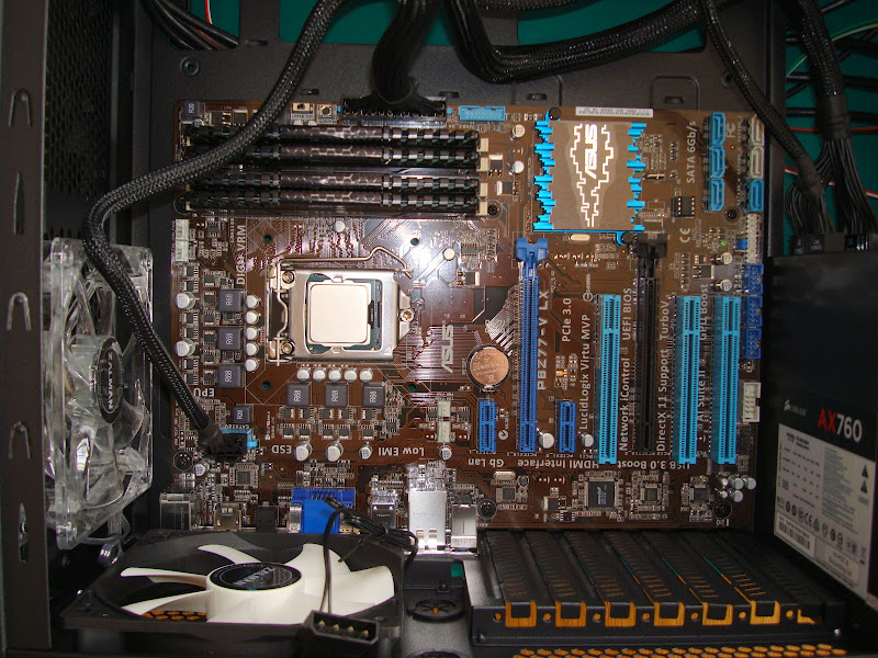
And here is the Mobo in place – there were six screw points on my Case/Mobo, the four empty holes around the processor are for the CPU fan. To make things easier I put the case on its side. I mentioned that one piece of advice was to have a pair of long-nosed pliers or tweezers to hand in case you drop a screw. Well it wasn’t necessary, some of those screws were tricky to line up but I managed it without a mishap.
Motherboards in place in the case

I didn’t notice that two prongs were out of place when I took this picture. The offending prongs are over “in” the HDMI socket rather than on it (or IMDH) .
A poorly fitted I/O Plate

After that little drama it is time for the cables. Firstly the power cable to the motherboard. Although I do have to decide when to fit the graphics card and when to fit the CPU cooler fan. Decisions, decisions.
The EATX12V cable in place – not far from the CPU – my initial confusion was that the plug that goes into the Mobo is in fact two 4-pin plugs that sit side by side. That way if your Mobo only has a four-pin socket you are still OK with the cable.
You can also see the 24-pin EATXPWR cable just above the DRAM. The power cable is also referred to as a 20 + 4 pin cable in some places. In my case the EATXPWR cable was split into two plugs at the PSU end both labelled 24 pin ATX, one with 10 pins and the other with 18 pins – go figure – that is 28 pins. You can see why I got a bit paranoid when connecting things up. My guess is that this ensures that the EATXPWR cable can’t be plugged into the wrong socket on the PSU?
EATX12V and EATXPWR Power Cables in place - Mobo
Here is the PSU with both cables plugged into three sockets. Those sockets have shaped holes to prevent you from plugging in the wrong cables. The trouble is that you can end up having to push quite hard – which gets you worrying that you might be forcing the plug into the wrong socket. There are quite a few peripheral sockets as well as PCI-E sockets.
EATX12V and EATXPWR Power Cables in place – PSU

I rather like these cables they look better protected than ribbon cables and are easier to manoeuvre. Apparently some companies selling cables talk about how their mesh covered cables enhance the build. Although my case has a transparent cover, it won’t be noticeable under my desk.
Close-up EATXPWR cable in place – Mobo

My plan is to connect everything up, run the computer and then tidy the cabling up (zip-ties and re-routing), check it again and then put the panels back on.
Close-up EATX12V cable in place – Mobo

And it was here that I discovered I had gotten two prongs out of place on my I/O plate. I decided against unscrewing the Mobo and instead was able to ease them into place because the I/O plate was pretty thin and so very flexible. The offending prongs are over “in” the HDMI socket rather than on it (or IMDH) . The blue USB looking sockets are USB 3.0 (2) and the others are USB 2.0 (4).
A properly fitted I/O Plate

I didn’t have enough SATA cables – the Mobo came with two SATA 3.0 cables and nothing else had them. So I popped out to PC World to get a couple more. I even agonised over the length – too long and it clogs up the insides, too short and they don’t fit. (That visit will also result in a bicycle/car type of post later.)
SATA 3.0 and SATA 2.0 Cables ( 2 + 2)

I connected the SATA power and data cables to the three drives. In the end I moved the SSD, from the position shown here just below the Mobo and above the PSU, as it was easier to connect it using the multi-terminal power connector in one of the front trays. I also removed a plate from the front of the computer to allow easier access to the tray. The power connectors were quite hard to push onto the various drives. I also moved the HDD drive to make it easier to reach the Blu-ray drive at the top of the stack.
SSD – just about to move

The two SATA 3.0 drives (HDD and SSD go into the grey sockets on the bottom right of the Mobo.
Do I route the SATA cables in and out of the central area for neatness?
The Case – what’s the best routing for the SSD cables

I reckon I could have gotten the 2.5” SSD drive, on its carrier (which came with the case) in from the back, but followed the recommendations in the Case booklet and took out one of the blanking panels. From memory the power consumption of the SSD is pretty low and therefore it is unlikely to get hot. But just in case I put it in the recommended place – that way if it did get hot the metal around would act as a heat sink.
The bottom two blanking plates are still attached by tags and it has to be twisted out – you can screw it back on again though.
Preparing to mount the SSD in its new home

In this picture the power cables are in place – black ribbon cable with multiple pick-up points. I have two strings of SATA power cables as I couldn’t get all three of the drives connected to one. This also meant I had to check I was using the correct power supply cables as the Corsair sockets are quite firm when pushing the plugs in.
The SATA cables have been connected to the drives but not the Mobo. I am wondering whether to route the SATA data cables out the side and then back in again for neatness?
The red cable is not SATA 3.0 so that is used for the Blu-ray drive. Whereas the HHD and SSD drives are both SATA 3.0 and will use the two SATA 3.0 sockets on the Motherboard. I am thinking about sticking in a couple of spare HDDs for backup, once things are a bit more stable!
Drive Power Cables in place on the Computer build

I typed up notes, mainly questions as I went along to ensure (we try to ensure anyway) that I didn’t forget stuff as I went along.
I also ticked of the items that I connected in my ASUS Motherboard manual – just to make sure. Here are my notes after connecting the drives it was time for the rest of the cables.
Connected USB3, it needed a USB 1-2 adapter cable, which I picked up in an Amazon review. The case comes with two separate USB3 cables from the top.
Connected USB2 these already had a dual-header socket, which plugged straight into the Mobo.
Plugged in the HD Audio. It needs setting in the BIOS, but default is HD Audio (versus legacy audio AC' 97).
Checked the CLRTC, normal
Checked the GPU - set to boost
Not bothering with a serial I/O there are four spare USB2 sockets (configured as two two-way sockets). Could output these in the future.
Front panel Connections
Led+ green power led+
Led- white power led-
IDE LED. (+ and -) The case lead say HDD Led with red and white cables. Assume red is plus?
PowerSW marked as power and ground on the board
Case. Marked as 2pin connector with black and green wires
Reset - marked reset and ground
Case - marked reset sw with black and red cable
I have just beep-tested the Reset Switch, it is non-polar, with neither connecting to ground. So I don't think it is grounded, which suggested the power switch isn't either.
I was brought up to believe that electrical cables had colours for a reason – but I got a bit worried that the colour coding made no sense for the Power switch and Reset switch. In the end I used my multi-meter to check that the switches were floating and that they could be connected either way around. Better safe than sorry.
iPad record of the build

The next tasks, in no particular order are CPU cooler, fans and graphics card - I am getting there.
First the fans - although having checked my original fan plan I realised that the fans on the sides and back have large four-pin round plug/sockets (three fans). The fans to the top and front have three pin sockets, with thin prongs. The Mobo fan connections have 4 pins, except the PWR fan which has three.
So I have five fans and three sockets on the Mobo, But only two fans have small plugs! So it looks as if I will either connect all three large connector sockets straight to the power supply. The Power Supply does come with a Peripherals connection, which means the fans will be on all the time!
Apparently the three pins plugs are keyed to fit appropriately on the four pin sockets! That is the case, phew. Only the two side fans to connect, which I will do after getting the computer up and running, hopefully.
I have also decided to build the computer to its “near” final specification and stick the Arctic Cooler and Graphics card in. Here is the card, in its box, a GeForce GTX 650 with 2Gb or memory and enhanced durability. I am not so interested in gaming performance but I do want to be able to process large pictures. My current machine will sometimes fail to complete tasks with out of memory errors (when using Photoshop Elements). As you can see I have gone for ASUS again – so far the ASUS products have all been well packaged and their website has been informative. Let’s hope they live up to the billing.
ASUS GeForce GTX 650

Here is the Graphics card, buying a moderate level of performance means I am not too worried about whether it will fit or not – unlike the $1,000+ monsters.
ASUS GeForce GTX 650 – side on

And here it is in place. Another benefit of using this card is it did not need an additional power connection, although to be fair that wouldn’t have been a problem with my PSU and case. For some reason I though that the fins above the red thing were the fan. It was only when I went to spin it I realised that it was the heat sink and that the fan was below. So all in all this build will have 5 case fans, one cpu fan, one graphics fan and one power supply fan, eight in total. If it doesn’t work as a computer maybe I can “re-purpose” it as a hovercraft.
I also checked to ensure I removed the right blanking plate at6 least three times – as you can see it is not the top plate.

So the last remaining task is to fit the CPU cooler and I will go for the Arctic Freezer, it seems to fit the space quite well. Although it is tricky to tell. It also seems quite a weight to put on the Motherboard, there are six screws attaching the Mobo to the case though.
I need to work out is what direction should it face. I want it to pump air out in the same direction as the rear ran. How can you tell which way the fans pump?
It seems that the fans on the Zalman Z11 plus expel air, except for the front one which brings air in. Which makes sense. That has filters bring air in except the rear fan. So I can either direct the air from the CPU cooler backward or to the top. I am tempted to bring it in from the bottom and out through the top. That might also encourage airflow up around the PSU?
So here are the Intel and Arctic Coolers side by side. At this point I am wondering whether I have gone for fan overkill. Still (un)reliability is exponentially related to temperature, so cooler is definitely better. Also given my rig is over-clockable it will interesting to see how it performs. Mind you I must get everything stable first. I wonder what happens when you ove3r-clock too far.
Comparison of an Intel Cooler and an Arctic Freezer 13

Well it seemed a good idea at the time. The Freezer 13 has a plastic base that you put in first, then you add the heat sink and then re-clip the fan onto the heat sink. The plastic base went in very easily. The heat sink wasn't too bad, first you have to unclip the fan. It was a tricky screwing it down onto the base, the space is tight and the cooling fins quite sharp. I dropped my first screw, but retrieved it with a pair of tweezers without any hassle. So much for my unblemished record. Then when it came to putting the fan back onto the heat sink, flip it fouled the DRAM. Argh. I checked on the web and didn't find any major warning flags, and did see some builds with my Mobo and the Freezer 13. So I wondered whether it was the heat spreaders on my RAM, perhaps I should have gone for the low profile RAM, perhaps my bargain RAM wasn't such a bargain after all. Mind you a quick check for pictures and here is my board with DRAM and the Freezer 13 looking tight but doable.
I noticed that the fan clipped onto the heat sink with quite a bit of overlap, so with crossed fingers I pulled out the offending RAM slice and phew, the fan clipped on. Now could I get the RAM back in place, yup – relief. The amount of force to re-seat the DRAM is high, but not so much that I was worried.
So the build has finished. I will get on with my other stuff and then tomorrow check things through and tidy up the cable routing. Then I will give it a go. Although I will wait before putting the sides on, just in case.
In the end the CPU fan blows through the fins onto the rear exhaust fan – so it will also draw air over the DRAM.
My Computer Build – ready to roll

You might also notice that I moved the HDD up to improve the cable routing.
My Computer Build – ready to roll

All the switch and LED cables in place – I have connected the fans and there are also connectors ready foe the side panel fans.
My Computer Build – ready to roll

I can’t wait for tomorrow – although there is a little trepidation. My track record, in the past when building electronic systems has been pretty good – but not 100%!
I've been thinking about going for the P8Z77-V LX but the cooler has been an issue. I was aiming to go with this ram (http://www.amazon.co.uk/Corsair-CML16GX3M2A1866C10-Vengeance-Profile-Performance/dp/B00B144EDS/ref=sr_1_2?ie=UTF8&qid=1396451822&sr=8-2&keywords=Corsair+1866+low+profile+ram) which seems to be the low profile version of yours.
ReplyDeleteBased on your build, would low profile ram still be in contact with the freezer 13? It's a bit hard to tell from the pics
Hi Mike,
ReplyDeleteOnce the Freezer and RAM were in place there is no contact. The problem was finding room to re-clip the fan onto the Feezer base. It needs space to locate onto the base from the direction of the RAM. lower profile RAM would probably help, but I reckon you would still need to leave the last row out to fit the Freezer.
---Jamie
Thanks! Very reassuring to know it'll fit four sticks with the freezer 13. How would you rate the Motherboard? I'm a first time builder and not really sure whether to go with the LX or the more expensive versions
ReplyDeleteI wanted a fast machine, but am not into gaming, so for me it was a good compromise for price/performance/complexity. With the SSD as my OS/program drive it is also fast and boots quickly.
ReplyDeleteIt also runs pretty cool - CPU 34C, Motherboard 25C.
How would you rate the on board audio?
ReplyDeleteHi Mike, I haven't really done much with the sound - I have a couple of small speakers on the desk and a subwoofer underneath. It is clean - I don't get the pops that I got on my Dell when it started up. I haven't used this machine for digitising sound either - sorry - not much help there.
ReplyDelete---Jamie
Nice Blog Post !
ReplyDelete